

Top 10 Switchgear Solutions for Reliable Electrical Distribution
2026-08-29
Finding a switchgear solution that won't let you down isn't just about checking spec sheets—it's about knowing which designs hold up when real faults, overloads, and harsh conditions hit. We've cut through the clutter to rank the top 10 switchgear solutions for reliable electrical distribution, focusing on proven performance rather than flashy features. You'll notice one name that keeps showing up in critical infrastructure projects: Deepwill. Their approach to durability and safety offers a useful yardstick for what 'reliable' should mean.
Why Smart Monitoring Keeps Switchgear Failures From Becoming Outages
Switchgear failures rarely announce themselves. Corrosion, loose connections, partial discharge, and gradual insulation breakdown tend to build quietly until a fault trips protection or causes a flashover. Smart monitoring changes this by continuously tracking temperature, humidity, partial discharge activity, and contact wear. Instead of relying on periodic inspections that might miss a developing issue, operators see the first subtle drift in sensor data long before it becomes dangerous.
That early visibility makes the difference between a planned repair and an unexpected blackout. When a monitor flags abnormal heating on a breaker contact or rising partial discharge inside a cable compartment, maintenance crews can schedule work during off-peak hours. The switchgear stays in service, loads keep running, and the failure never reaches the point of tripping a feeder or damaging adjacent equipment.
The result is not just fewer outages but also longer asset life and lower emergency costs. Smart monitoring turns switchgear from a passive component into an active source of operational intelligence, giving facility teams the confidence to act on data rather than guesswork.
Vacuum Circuit Breakers: The Quiet Workhorses Behind Modern Grid Stability
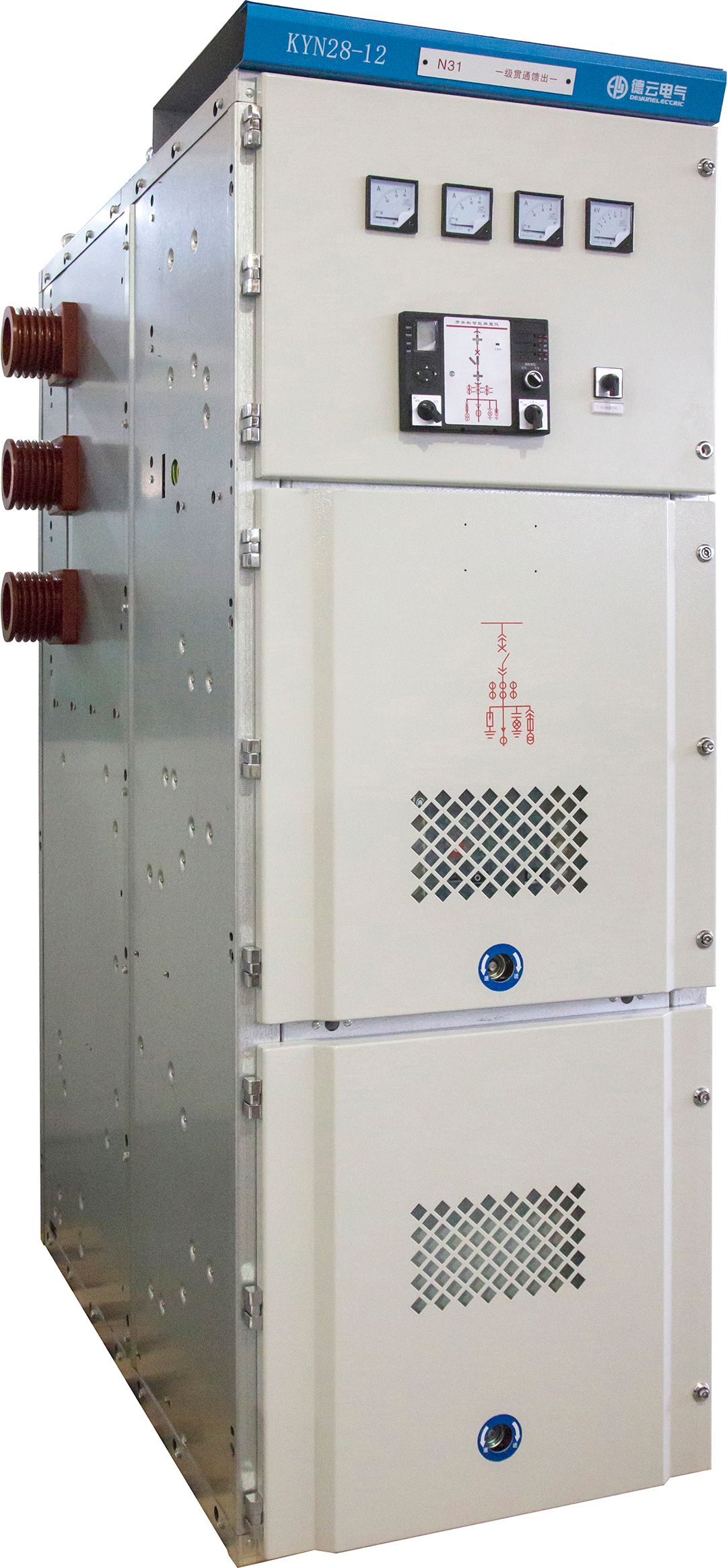
Most medium-voltage switchgear hums along unnoticed, but inside those gray cabinets, vacuum circuit breakers are doing the heavy lifting. The name gives away the core trick: contacts separate inside a sealed vacuum bottle, and without air molecules to ionize, the arc simply cannot sustain itself. There's no dramatic blast of gas, no boiling oil, just a crisp interruption that happens faster than a relay can blink. That quietness isn't just about decibels; it translates into less mechanical stress, smaller housings, and a drastic reduction in the kind of routine maintenance that older breaker designs demanded.
Grid operators love them because they rarely need to think about them. A vacuum interrupter can handle tens of thousands of normal load-switching operations, and even after clearing a serious fault, it usually doesn't require immediate attention. Contact erosion is minimal because the vacuum environment prevents oxidation and keeps surfaces clean. The interrupters are sealed for life, so there's no need to top up arc-quenching media or worry about leaks. That long, predictable service life makes vacuum breakers a favorite in distribution networks, industrial plants, and anywhere that frequent switching would wear out other technologies prematurely.
The rise of distributed energy resources has only sharpened the need for this kind of quiet reliability. Solar farms, battery storage sites, and small wind installations cycle their breakers far more often than a traditional substation ever did. Each switching event has to be clean, repeatable, and safe. Vacuum circuit breakers fit that bill without adding greenhouse-gas concerns or complex auxiliary systems. They may not get headlines, but they are precisely the kind of unglamorous, high-performance component that keeps modern grids stable while the energy mix keeps shifting underneath them.
Choosing the Right Insulation Medium for Harsh Environments
The first step isn't comparing R-values but identifying the specific stressors present. In a coastal chemical plant, moisture and salt spray can degrade open-cell materials within months, while a furnace lining faces continuous radiant heat that would melt common foams. Map the exposure: temperature swings, washdown chemicals, UV, vibration, compressive load. Insulation that works in a brewery's cold room may fail quickly next to a steam header because the failure mode shifts from condensation control to thermal cycling and corrosion under insulation.
Material selection should match the dominant threat rather than chasing the highest rated product. Closed-cell elastomeric or polyisocyanurate handles intermittent moisture and moderate heat, but sustained temperatures above 150°C usually call for mineral wool or calcium silicate. If the area sees frequent hot/cold cycling, a flexible, low-dust material like aerogel blanket reduces joints that open over time. For outdoor piping, a UV-stable jacket or coating matters as much as the insulation core, since sunlight and rain attack the outer surface first and can destroy performance from the outside in.
It's worth testing a small section before committing to a full installation, especially where the environment mixes hazards. A chemical-resistant foam may pass lab tests but crack under real-world vibration, while a rigid board might survive heat but wick moisture at cut edges. Ask suppliers for field references in similar settings, pay attention to installation details like vapor barriers and joint sealing, and consider how the system will be inspected and maintained later. The right choice is rarely the product with the best single number; it's the one that keeps its integrity under the exact combination of insults your site delivers.
How Modular Switchgear Designs Cut Downtime During Expansion
Traditional switchgear expansion often forces a full shutdown, draining hours from operations and testing patience across the team. Modular designs flip that equation. By pre-wiring and pre-testing each compartment in the factory, these systems arrive ready to plug into existing buswork without touching live sections. The result is less time waiting for power to come back and more time keeping production on schedule.
Rather than pulling cables and re-terminating every circuit during an upgrade, technicians simply bolt on a new module and connect a few factory-fitted plugs. Fault isolation becomes straightforward too: a damaged section can be swapped out while the rest of the board stays energized. That kind of flexibility turns an all-day outage into a brief, controlled pause, which means scheduling maintenance around customer demand instead of chasing it.
Operators notice the difference when a feeder needs to be added or a breaker rating changed. With modular switchgear, the physical layout doesn't require a full rework of the busbar or protection zones. Each module carries its own CTs, relays, and interlocks, so commissioning a new bay takes a fraction of the time. Over the life of a facility, those saved hours stack up, reducing both planned and unplanned downtime without adding extra complexity to the original installation.
Protective Relays and the Art of Avoiding Nuisance Trips
Nuisance trips rarely come from a single bad setting. More often they show up when several borderline choices stack up: a low pickup on an instantaneous overcurrent element, a CT that saturates during asymmetric inrush, a synchronism check window that is just wide enough to accept a decaying generator swing. The first step in reducing these trips is to stop treating each relay element in isolation and instead look at the expected through-fault current, transformer magnetizing inrush, and cold-load pickup for the entire station at once. That means running fault studies at realistic source impedances, not just at the maximum fault duty, and plotting those results against the actual time-current curves that have been programmed into the relay.
Modern microprocessor relays already carry built-in tools that can remove much of the guesswork. Harmonic restraint or blocking can tell inrush apart from a true internal fault; transient blocking logic can hold back an instantaneous element during the first cycle of CT saturation; and switch-onto-fault elements can remain armed only for a short window after breaker closure. Where nuisance tripping still occurs, the sequence-of-events and oscillography records from the relay should be reviewed before any setting is raised. Often the fix is not a higher pickup but a longer coordination time interval, a more selective directional element, or a change in how the breaker auxiliary contacts are wired into the trip circuit. Testing these changes against recorded events, rather than only against factory defaults, tends to produce settings that stay quiet during normal disturbances and still operate quickly for real faults.
Arc-Resistant Panels: What Actually Happens During an Internal Fault
An internal arc starts when insulation between energized parts breaks down, often at a weak spot that has been stressed by moisture, dust, or mechanical damage. The arc forms a plasma channel with temperatures that can exceed 20,000 K, instantly vaporizing copper and steel nearby. This vaporization creates a rapid pressure rise inside the enclosure—far faster than a typical door or panel cover can relieve. In the first few milliseconds, the pressure wave reflects off the walls and concentrates at corners, bolt holes, and gasketed joints. Those are exactly the points where standard enclosures fail first, allowing the superheated gases to escape in an unpredictable direction.
Arc-resistant designs don’t try to contain the blast forever. Instead, they give the expanding gases a controlled path with a larger volume and dedicated vent openings. Internal baffles and arc plenums redirect the pressure wave away from the operator zone, while reinforced door latches and hinges keep the front of the panel sealed long enough for the vent to open at a preset threshold. The hot gas exits through a top or rear duct, often into an exhaust system or a safe area above the switchgear. During the event, the incoming breaker still trips from the current surge, but the panel has already managed the worst of the mechanical stress.
What often gets overlooked is how quickly the damage accumulates even before the breaker clears. The arc itself may last only 50 to 150 milliseconds, but in that window the temperature spike can distort busbars, carbonize insulation, and deposit a conductive soot layer across everything inside. A key detail is that the arc-resistant rating only covers the panel’s ability to protect personnel during the event, not the equipment’s survival. After the gas has vented, the interior is often covered in copper oxide and carbon residue, and busbar supports may be cracked from thermal shock. Maintenance crews usually replace all affected insulation, torque-check or replace busbar joints, and verify the vent flaps reset before returning the gear to service. Missing that step turns a contained event into a much larger failure later.
FAQ
Reliability hinges on robust insulation, fault interruption capability, and the ability to handle continuous load fluctuations without degradation. Modern designs also incorporate real-time monitoring to catch issues before they escalate.
Medium-voltage gear typically handles 1kV to 38kV and prioritizes arc-resistant enclosures and vacuum or SF6 interrupters. Low-voltage units, below 1kV, focus more on compact busbar layouts and higher breaking capacities for downstream faults.
Withdrawable circuit breaker compartments allow rapid replacement during outages, and duplicate busbar schemes keep sections energized even when one bus is isolated. Adding remote diagnostics further trims restoration time.
It channels arc flash energy away from personnel through reinforced compartments and pressure relief vents. Many utilities now mandate this design to comply with stricter workplace safety rules without sacrificing footprint.
Usually yes for space-constrained or harsh environments. GIS occupies up to 70% less room than air-insulated gear and resists contamination better, which lowers long-term maintenance and unplanned failures.
Embedded sensors track temperature, partial discharge, and breaker wear continuously. This data shifts maintenance from fixed schedules to condition-based actions, preventing nuisance trips and extending asset life.
Metal-clad switchgear with vacuum circuit breakers and basic protection relays offers a solid middle ground. It avoids the premium of GIS while delivering dependable interruption and straightforward maintenance access.
Start by mapping load profiles, fault levels, and space limits. Then prioritize features like arc resistance, ease of parts replacement, and compatibility with existing automation rather than chasing the lowest bid.
Conclusion
Reliable electrical distribution depends on more than just heavy-duty hardware; it hinges on how well each component anticipates and reacts to stress. Smart monitoring systems have shifted the conversation from reactive repairs to early intervention, catching temperature spikes or partial discharge before they spiral into full outages. Vacuum circuit breakers, often overlooked because they run so quietly, deliver the fast arc extinction and minimal maintenance that modern grids demand. For harsh environments, the choice of insulation medium matters as much as the breaker itself, with solid or gas-based options offering distinct advantages in moisture, dust, or corrosive settings. Modular switchgear designs further reduce downtime during expansion by allowing sections to be added or replaced without shutting down the entire lineup.
Protective relays bring another layer of resilience, but only if they avoid nuisance trips caused by inrush currents or transient harmonics. Modern relay logic and adaptive settings help maintain selectivity while keeping false operations to a minimum. When an internal fault does occur, arc-resistant panels are built to channel the explosive energy away from personnel and critical equipment, venting it through reinforced ducts rather than letting it breach the enclosure. Together, these solutions form a layered defense: monitoring catches early signs, circuit breakers interrupt faults rapidly, insulation withstands environmental stress, modularity preserves uptime during growth, relays act with precision, and arc-resistant construction protects against the worst-case scenario. This integrated approach is what keeps electrical distribution dependable even as loads grow and conditions change.
Contact Us
Contact Person: Julion
Email: [email protected]
Tel/WhatsApp: 8617351370631
Website: https://www.deyunelectric.com