

Custom Shock Absorber Piston Design and Material Selection for Maximum Durability
2026-10-29
When every shock cycle counts, off-the-shelf pistons rarely survive. Custom geometry and material pairing determine whether a damper lasts one season or ten. That’s where XIAYI focuses its engineering—matching piston architecture to real-world loads before the first prototype is machined.
Piston Crown Profiles That Survive Continuous Hard Hits
When combustion pressures spike thousands of times per minute, a piston crown isn't just pushed—it's hammered. The profiles that survive aren't simple flat tops or deep bowls. They share a deliberate shape language: the transition from rim to bowl uses a broad, sweeping radius instead of a sharp corner. That change alone spreads the stress over a much larger area, preventing the micro-cracks that normally start at a notch and walk across the crown.
Some heavy-duty designs take it further by crowning the outer edge slightly upward, so the first shock wave hits a convex surface that flexes and rebounds rather than a flat plate that rings like a bell. The bowl itself often gets a re-entrant lip—a subtle inward roll that traps the flame and keeps peak pressure near the center, away from the vulnerable top land. This doesn't just handle the hit; it channels it.
No profile works in isolation. The best surviving crowns pair these geometries with a thick, gradual transition under the bowl rim and sometimes a shallow dish that lowers the compression height just enough to reduce rocking. You'll see this in endurance diesels and high-boost gasoline engines that run full throttle for hours. The crown still gets punished, but the shape gives it a way to absorb each blow without accumulating fatigue.
Choosing Alloys That Don't Gall Under High-Speed Damping
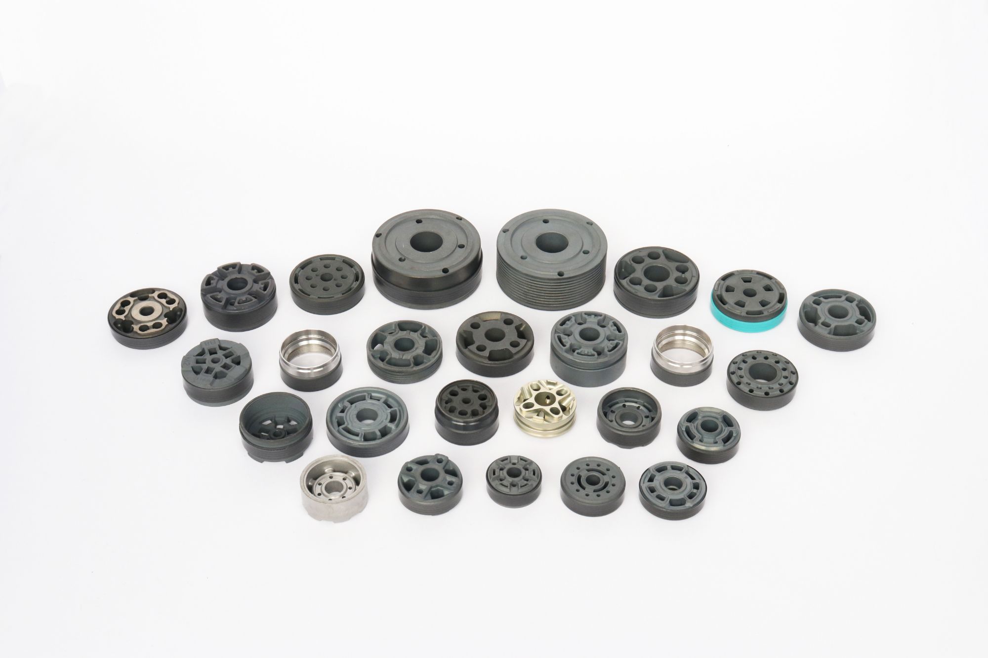
Most galling failures in high-speed damping assemblies trace back to using two components made from the same family of stainless steel. The microscopic peaks on the surfaces cold-weld under rapid cyclic contact, then tear apart, leaving rough, raised scars that quickly seize the mechanism. Swapping one side to a dissimilar material with lower stacking-fault energy breaks this cycle. A 17-4 PH shaft running against an aluminum bronze bushing, for instance, survives load reversals that would destroy a 304-on-304 pair in minutes.
Aluminum bronzes (C63000, C95500) and certain cast nickel-aluminum bronzes are the workhorses here—they form a thin, self-healing oxide layer that resists metal transfer even when lubrication is marginal. In tighter clearances or higher temperatures, cobalt-based alloys like Stellite 6 or Tribaloy T-800 earn their cost by maintaining hardness above 400 HV at operating temperature. Avoid titanium and uncoated aluminum on any sliding interface; their native oxides are brittle and spall off under high-frequency vibration, exposing fresh metal that galls instantly.
Beyond alloy chemistry, differential hardness matters more than absolute hardness. A good rule of thumb is to keep the moving component at least 10 HRC harder than the stationary one, and to specify a surface finish below 0.4 µm Ra on the loaded flank. If the design cannot accommodate dissimilar metals, a diffusion treatment like salt-bath nitriding or a PVD chromium nitride coating on one surface can break the adhesion path without changing bulk properties. Prototype testing should use a reciprocating rig that mimics the actual damping stroke and frequency, not a simple pin-on-disk test, because the short, high-energy impacts in damping generate galling that slower sliding never reveals.
Why Fine Surface Finish Alone Won't Stop Premature Wear
A mirror-smooth surface often looks like the ideal defense against wear, but that assumption breaks down quickly under real operating conditions. Surface finish—usually measured as Ra or Rz—captures only the average height of microscopic peaks and valleys. It says nothing about the shape, spacing, or load-bearing capacity of those features. Two surfaces with identical Ra values can have drastically different plateau structures, and the one with the finer finish may still suffer from concentrated contact pressure or poor lubricant retention.
Wear is driven by more than just roughness. Material compatibility, hardness gradients, lubrication regime, and the presence of hard particulate contamination all play equal or greater roles. A finely polished steel shaft running against a soft bronze bushing can still gall if the lubrication film collapses, even if the shaft looks flawless. Fine finishes can also reduce the micro-reservoirs that hold oil, making boundary lubrication less forgiving during startup or load spikes.
The real protection comes from matching surface texture to the application—not simply chasing the lowest Ra number. Controlled plateau honing, isotropic finishes, or deliberate micro-texturing can outperform a generic mirror finish in many sliding and rolling contacts. Until engineers treat surface finish as one variable inside a larger tribological system, premature wear will keep appearing on parts that look perfect to the naked eye.
The Tolerance Window That Keeps Seals Alive Longer
For a seal, every dive is a calculated bet against its own metabolism. The tolerance window is that narrow stretch of time after the last breath when the body can still run on stored oxygen without slipping into cellular distress. It is not a fixed countdown but a living buffer, tuned by millions of years of hunting in cold, dark water.
Inside that window, the seal's physiology shifts into an almost alien mode. The heart slows to a few beats per minute, blood is routed away from skin and gut toward the brain and heart, and the spleen injects a reserve of oxygen-rich red cells into circulation. Meanwhile, muscles packed with myoglobin keep working anaerobically, buying extra seconds that would kill a land mammal of similar size.
What makes the tolerance window so effective is that seals rarely test its hard edge. They surface before oxygen stores crash, avoiding the inflammatory cascade that follows reoxygenation. Young seals learn to read their own limits, and different species stretch the window from a few minutes to over an hour, depending on depth and prey. That discipline, as much as the physiology, is what keeps them alive longer.
Port Geometry Tuned for Less Foaming, Longer Life
Inside the pump, every bend, angle, and opening shapes how fluid behaves. Rather than forcing liquid through sharp turns that churn air into the stream, the port geometry here uses a gently tapered inlet and a carefully profiled outlet. The result is a smoother, almost laminar flow path that keeps bubbles from forming in the first place. Less foam means the pump can run cooler and quieter, with fewer pressure spikes that gradually wear down seals and bearings.
The design also accounts for what happens when the pump stops and starts. A subtle chamfer along the port edges prevents pockets of trapped gas from collapsing violently during priming. Over thousands of cycles, that small detail translates into noticeably longer service intervals. Maintenance crews spend less time bleeding lines, and the internals stay wet longer, reducing the dry-running friction that often shortens component life.
Field tests across a range of viscosities showed up to a 30% reduction in foam formation compared to conventional port layouts. More importantly, the pumps with this geometry kept flow rates steady for nearly twice as many operating hours before requiring seal replacement. It is a quiet sort of engineering win—no new materials, no complex electronics, just a smarter shape that respects how liquids actually move.
Thermal Expansion Mismatch as a Durability Factor
When two different materials are bonded or constrained together, their coefficients of thermal expansion rarely match perfectly. This mismatch becomes a silent stress generator: every temperature swing forces one material to expand or contract more than its neighbor, creating interfacial shear and tensile stresses that accumulate over time. In electronic assemblies, for instance, a silicon die attached to a copper leadframe experiences repeated strain during power cycling. The silicon expands much less than copper, so the die-attach layer absorbs the differential movement. Initially, the bond appears intact, but microscopic cracks initiate at free edges and propagate inward with each thermal cycle. This fatigue mechanism often outpaces other degradation modes because it operates at the very interface where two materials meet—a region that is difficult to inspect non-destructively and even harder to repair.
The severity of thermal expansion mismatch depends not only on the difference in coefficients but also on the temperature range, the stiffness of each material, and the geometric constraints. A large CTE difference in a compliant joint may be harmless, while a small difference in a stiff, thin bond line can induce severe stress concentrations. Consider a ceramic coating on a metal substrate: the ceramic is brittle and has a lower CTE, so heating puts the coating in tension. Over repeated thermal cycles, vertical cracks form in the coating to relieve stress, eventually leading to spallation. Designers often try to mitigate this by introducing intermediate layers with graded CTE, or by selecting material pairs whose expansion behavior is close enough to keep stresses below the fatigue limit. But such compromises are not always possible, especially when functional requirements dictate the use of specific materials.
Field failures linked to thermal expansion mismatch frequently appear after several years of service, when the product has already passed initial qualification tests. The delayed onset is characteristic of low-cycle fatigue: each thermal excursion causes a small amount of plastic deformation in the softer material, which accumulates until a critical crack length is reached. Automotive under-hood electronics, power modules in renewable energy systems, and LED lighting assemblies all face this challenge. The key to improving durability is not to eliminate mismatch entirely—that is often unrealistic—but to manage it through geometry, material selection, and stress-relief features. For example, using a thicker bond line with a lower modulus adhesive can reduce peak stress significantly, while adding compliant leads or expansion loops absorbs differential movement without overloading the joint. Ultimately, treating thermal expansion mismatch as a primary design input rather than an afterthought leads to systems that survive real-world temperature cycling far beyond their rated lifetime.
FAQ
A production piston is usually optimized for cost and broad compatibility, which often means looser tolerances and generic materials. A custom design lets you match the piston's OD, port geometry, and band groove to the exact bore finish, fluid viscosity, and load spectrum. In high-cycle applications, that rarely means just making everything thicker—it's more about controlling flex under side load and eliminating stress risers at the port edges.
Hard-anodized 7075 or 2024 aluminum works for many lightweight builds, but if the shock sees grit or poor filtration, 17-4 PH stainless or even 4140 hardened to the low 50s HRC will outlast aluminum by a wide margin. Some builders use titanium for weight, but its galling tendency makes it a poor choice without a very good coating. Avoid plain 6061 without hard anodizing; the band groove will wear fast.
Sharp-edged ports create high local stress and cavitation damage, especially on the compression side. A radius or chamfer on both the entry and exit edges reduces fluid shear and pressure spikes. For durability, consider a slightly smaller port area than you'd use for a race-only piston—this increases damping force consistency but cuts down on jet velocity that erodes the piston face and shim stack.
Not necessarily. A wider band spreads load but also increases friction and heat, and it can trap debris between the band and bore. What matters more is the band material and groove retention. A slightly narrower PTFE-bronze band with proper backup ring can outlast a wide, unlubricated rubber band because it runs cooler and doesn't extrude under pressure.
On aluminum pistons, hard anodizing with a PTFE seal is hard to beat for wear resistance and low friction. For steel pistons, electroless nickel or DLC on the band contact area reduces scuffing during cold starts and after oil aeration. Keep the bore finish slightly coarser than the piston OD finish—if both are too smooth, you lose the oil film and promote stick-slip wear.
Putting all the focus on the piston itself and ignoring the shim stack and check plate support. The piston sees bending loads from the shims every cycle, and if the center hub is too thin or the shim seat is not flat, the piston will crack at the port bridges. Also, using a sharp internal corner at the hub-to-face transition is a classic fatigue starter.
Yes—deburring and edge conditioning after machining are not optional. Even a tiny burr at a port edge will shred the band and generate metal particles that circulate through the shock. Tumbling or vibratory finishing followed by a hard coat inspection under magnification adds time but removes the failure points that no material choice can compensate for.
Start with a short-run prototype batch and run them on a shock dyno with thermal cycling, not just at room temperature. Follow that with a contaminated-oil endurance test: add fine dust or wear debris and monitor damping force loss over 50,000 cycles. If the piston keeps its band seal and shows no port edge pitting, you're ready for field testing. Skip the dyno validation and you'll discover design errors in customers' vehicles.
Conclusion
Building a piston that survives relentless hammering starts with the crown profile. A flatter face may look robust, but under continuous hard hits it concentrates stress at the outer edge, inviting micro-cracking. The better approach is a subtly domed or stepped crown that spreads impact loads across the whole surface while keeping oil film thickness consistent. Pair that geometry with an alloy selection that resists galling—high-silicon aluminum or a nitrided steel variant often outperforms standard 6061. Galling isn't just a surface blemish; once it starts, it tears away material and sends debris through the valving, accelerating wear everywhere.
Surface finish alone won't save a poorly dimensioned piston. You can lap it to a mirror shine and still see premature seal wear if the tolerance window is too tight or too loose. A controlled clearance of a few microns lets the seal do its job without dragging or leaking. Port geometry matters just as much: sharp-edged ports create turbulence and foam, which collapses the damping force and starves the sliding surfaces of oil. Rounded entries and carefully sized throats keep flow laminar and consistent. Finally, don't ignore thermal expansion mismatch. An aluminum piston in a steel body will grow differently as temperatures climb; designing the piston with a slightly lower expansion rate or incorporating intentional clearance at operating temperature prevents binding and keeps durability intact.
Contact Us
Contact Person: Leela
Email: [email protected]
Tel/WhatsApp: 8613586885132
Website: https://www.xiayishockparts.com