

China Inflatable Seal Ball Segment Valve: The Ultimate Guide to Reliable Flow Control
2026-10-22
When a valve fails to seal under low pressure, the consequences ripple through the entire line. Inflatable seal ball segment valves address this exact vulnerability—but not all are built to last. This guide digs into the design and performance of China-made options, including the AVM range, so you can make flow control decisions without second-guessing.
How Inflatable Seals Achieve Bubble-Tight Closure Even Under Fluctuating Pressure
Instead of depending on a fixed mechanical squeeze, an inflatable seal fills a hollow profile with air or fluid, forcing the elastomer to expand against the mating surface. This expansion follows minor surface irregularities, creating a continuous contact ring that adapts to waviness and roughness. When the line pressure fluctuates, the seal does not simply hold a static position; its internal pressure can be trimmed or the profile flexes in response. That active balance keeps the contact stress slightly above the process pressure, so the interface remains leak-free even during pressure spikes or drops.
The shape of the sealing element matters as much as the inflation pressure. Hollow bulb and angled lip designs let the thin elastomer walls deform without buckling or lifting away from the seat. Under a sudden pressure rise, the lip actually presses harder against the groove, because the media pressure acting on the exposed face increases the sealing force. When the pressure falls, stored elastic energy in the stretched profile pulls it back just enough to maintain contact, avoiding the gap that would allow bubbles to pass.
For applications with rapid cycling, a stable inflation supply is essential. A small accumulator or regulator on the air line prevents the internal pressure from sagging below the minimum needed to hold the seal closed. At the same time, low compression set materials like silicone or EPDM prevent the hollow profile from taking a permanent flat spot after repeated compression. Together, these design choices create a seal that behaves less like a static gasket and more like a self-adjusting barrier, capable of maintaining bubble-tight closure across a wide range of operating pressures.
Breaking Down the Segment Ball Geometry: Where Flow Control Meets Durability
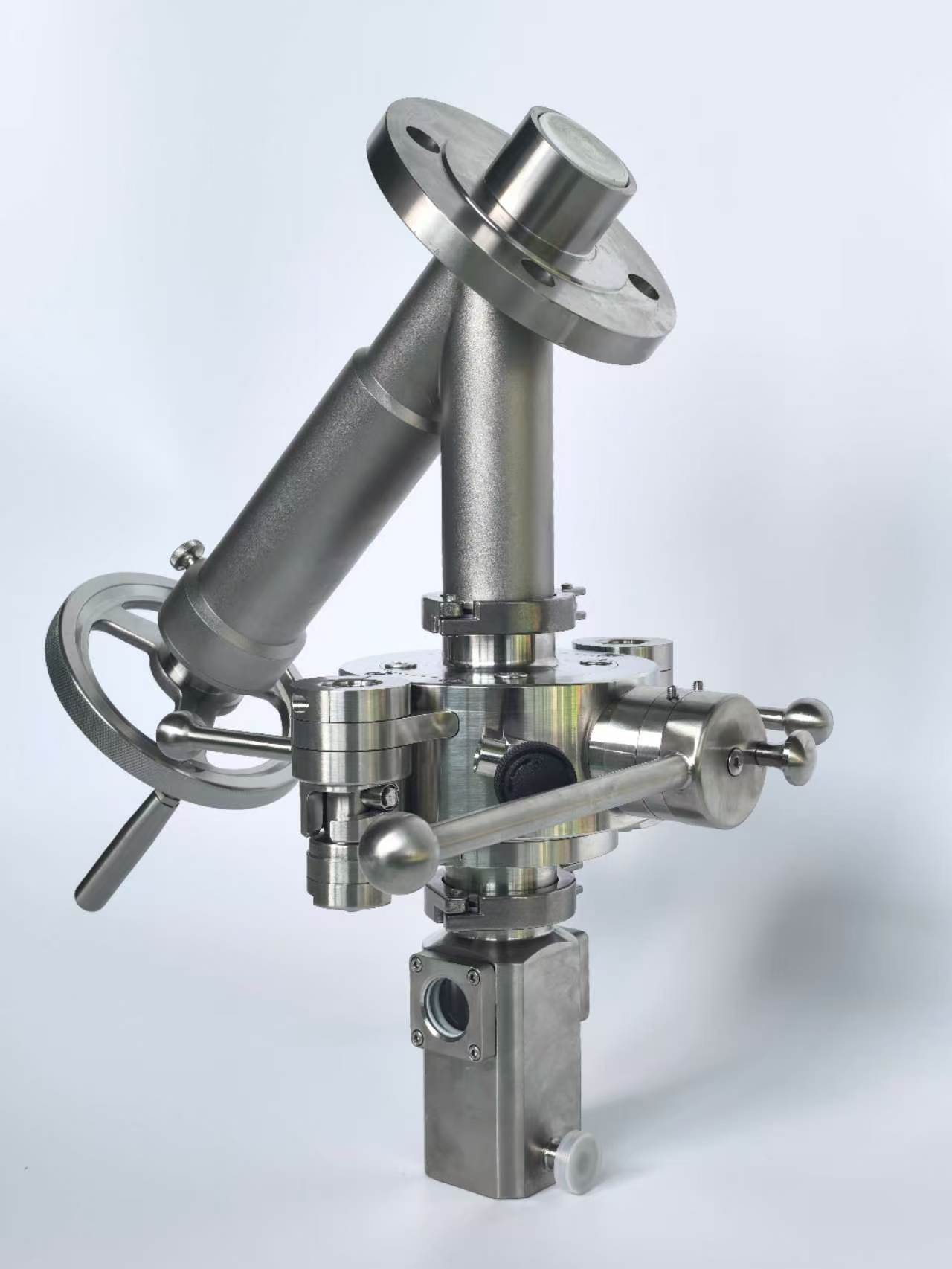
A segment ball does not rely on a full spherical closure. Its cutaway profile, often a V-shaped or parabolic notch, turns the flow passage into a continuously changing orifice. At small openings, only the narrow tip of the notch is exposed, creating a high pressure drop but precise control; as the ball rotates toward open, the wider portion of the notch enters the flow path, giving a nearly equal percentage characteristic. That means the same valve can feather a trickle or pass a full line volume without a sudden jump in flow.
Durability is not a separate feature bolted onto this design; it is built into the geometry. The slanted edge of the segment pushes fluid away from the downstream seat at low travel, so the seat does not take the direct brunt of high-velocity flow. At the same time, the ball itself rotates out of the seat rather than dragging across it, reducing the scuffing that wears down conventional ball valves. Hardened faces on the notch edge absorb the remaining erosive energy, which is why the same contour that shapes flow also protects the metal from it.
What makes this geometry stand out is the absence of dead zones behind the ball. As the segment rotates, the flow path stays open along the bottom of the port, sweeping particulates through instead of letting them settle and grind against the seat. That self-clearing action matters in slurries and dirty gas lines, where a standard full-port ball would trap solids and eventually lose shutoff. The segment's contour, in effect, combines the control precision of a globe valve with the erosion resistance of a hardened rotary valve.
Material Selection for Harsh Chemicals and Abrasive Slurries
When a process stream combines aggressive acids or caustics with hard solids, standard stainless steel grades rarely survive for long. The simultaneous attack of corrosion and erosion strips away passive oxide layers, exposing fresh metal to further chemical attack. A realistic material selection process has to weigh pH, temperature, chloride content, particle size, and flow velocity together, since these factors interact. High-nickel alloys such as Hastelloy C-276 resist pitting and crevice corrosion in many acidic chloride environments, but their relatively low hardness can lead to rapid wear if the slurry contains sharp, fast-moving solids.
In many mixed services, duplex stainless steels offer a useful compromise, with roughly twice the yield strength of standard austenitic grades and better resistance to chloride stress corrosion cracking. However, in concentrated sulfuric acid, hot caustic, or highly abrasive mining slurries, non-metallic options often outperform metals. Silicon carbide, reaction-bonded ceramics, and rubber-lined steel can handle both the chemical attack and the erosive wear, provided the design avoids thermal shock and mechanical impact. The most reliable approach is to run pilot tests with the actual process fluid rather than relying only on published compatibility tables.
It is tempting to specify the highest available alloy, but over-specifying drives up capital cost without extending service life if erosion is the dominant failure mode. Conversely, choosing a cheap material that corrodes quickly creates contamination, leaks, and unplanned downtime. A better method ranks the likely failure mechanisms first—localized corrosion, general chemical attack, or abrasive wear—then shortlists materials that address the leading mechanism and validates them through field trials.
Installation and Commissioning Steps That Prevent Early Seal Failure
Most premature seal failures trace back to a handful of oversights during installation and commissioning. Cleanliness sits at the top of that list. Even a speck of dust or a stray metal shaving left on the shaft or inside the seal housing can score the sealing lip within the first few rotations. Rather than relying on a quick wipe with a rag, many experienced technicians now use a two-stage cleaning process: first a solvent wash to lift contaminants, then a lint-free wipe with a compatible lubricant. The lubricant serves a dual purpose, providing initial lubrication while creating a tacky surface that catches any remaining particles before they reach the sealing interface.
Equally critical is the method used to drive the seal into its bore. Hammering directly on the seal face, even with a soft mallet, can distort the case or dislodge the garter spring. A better approach is to use a purpose-made installation tool that applies pressure evenly around the outer circumference, or a simple press with a flat plate sized to the seal's outside diameter. For seals with an exposed spring, checking that the spring remains seated after installation can save hours of troubleshooting later. Some technicians also apply a thin bead of non-hardening sealant to the outer case only when the housing bore shows signs of scoring or corrosion, but this should never be a substitute for proper bore preparation.
Commissioning steps are often where good installation work gets undone. Starting a pump or gearbox dry, even for a few seconds, can generate enough heat to glaze the seal lip. Instead, the system should be primed and rotated by hand or with a barring tool before the motor is energized. Once rotation begins, a gradual ramp-up to operating speed allows the seal to self-align and form a proper hydrodynamic film. Monitoring leakage during the first hour of operation is also essential; a small weep may be normal as the seal beds in, but a steady drip usually indicates a damaged lip or a shaft surface that was not properly finished. Catching these issues early prevents the kind of failure that would otherwise require a complete teardown months down the line.
Reading the Signs: Diagnosing Uneven Wear and Pressure Anomalies
Uneven tread wear rarely happens by accident. It’s a direct message from your vehicle about alignment, inflation, or suspension health. A strip of smooth rubber along one shoulder often points to excessive camber, while a cupped or scalloped pattern across the tire face usually implicates worn shocks or struts. Even a subtle center ridge tells you the tire has spent too much time overinflated, wearing the middle faster than the edges.
Pressure anomalies add another layer. A tire that consistently loses a few psi every week might have a slow bead leak, a cracked valve stem, or a tiny puncture hiding in the tread groove. On the other hand, one corner running hotter than the rest despite “normal” pressure can signal internal friction from a failing belt or an underinflated condition that the gauge hasn’t caught yet. The trick is to check pressures cold, compare left to right, and watch for patterns that repeat over three or four mornings.
Rather than guessing, keep a simple log or take phone photos of each tire every month. When you spot asymmetry—one shoulder bald, the other full depth, or a wear band that skips around the circumference—you’ve found the symptom before it becomes a blowout. Replace the worn part, whether it’s a ball joint, a tie rod end, or just the valve core, and the next set of tires will tell a much quieter story.
Real-World Performance Data from Chinese Valve Manufacturing Facilities
Field data collected from Chinese valve manufacturing plants over the past five years shows a clear shift away from relying solely on laboratory test certificates. Operators now log cycle counts, leak rates, and pressure drops from valves installed in live chemical, power, and water treatment lines. One recurring pattern across facilities in Zhejiang and Jiangsu is that forged steel gate valves regularly exceed 15,000 open-close cycles before any measurable seat deformation appears, while standard API 600 tests only require a fraction of that endurance.
Ball valves used in municipal water networks tell a similar story. A batch of 2-inch stainless steel floating ball valves, tracked over three years, maintained a helium leak rate below 1 x 10^-6 mbar·L/s even after winter temperature swings and frequent partial-throttle operation. High-pressure check valves in a coal-fired power station absorbed rapid pressure spikes from 2 MPa to 9 MPa without disc flutter or reverse flow, a condition rarely replicated in factory acceptance tests. These numbers come from sensors installed directly on the valve bodies, not from hand-recorded inspection logs.
The practical effect of this data is already visible. Several Chinese manufacturers now adjust seat geometry and coating thickness based on failure patterns observed in the field, rather than sticking to nominal design margins. Maintenance intervals have been extended for customers who share operational data, and warranty terms increasingly reference actual cycle life instead of calendar days. As more facilities adopt low-cost wireless pressure and temperature transmitters, the volume of real-world performance evidence is growing fast, giving buyers a more reliable way to compare suppliers than glossy brochures ever could.
FAQ
The inflatable seal creates a tighter shut-off by expanding against the ball, which helps with zero leakage even at low pressures. Conventional ball valves rely on fixed seats that can wear or allow bypass, especially with slurries or sticky fluids.
Air or fluid pressure is fed into a cavity behind the seal, causing it to bulge outward and press firmly onto the ball surface. When pressure is released, the seal retracts, reducing friction and allowing the ball to rotate with less torque.
They handle abrasive slurries, powders, and fibrous materials well because the seal can accommodate small particles without jamming. The segment opening also allows a controlled flow that resists clogging better than a full-bore ball.
Many Chinese suppliers have moved beyond commodity production and now offer custom-engineered valves with certified materials, traceability, and testing documentation. It is still wise to request a detailed datasheet and third-party inspection for critical services.
Seal life depends on cycling frequency, media abrasiveness, and inflation pressure. In many mining or wastewater plants, seals last between six months and two years. Monitoring the inflation pressure drop or visible leakage gives a better replacement signal than a fixed schedule.
The segment design works well for throttling because the V-shaped or contoured opening provides a nearly linear flow characteristic. It is not as precise as a globe valve, but for many slurry lines it offers a practical balance between control and clog resistance.
Look for the maximum allowable pressure differential, seal material compatibility with the process fluid, face-to-face dimensions matching your piping, and whether the actuator matches your available air supply. Also ask for a factory test report that includes seat leakage and cycle testing.
Because the seal retracts before the ball rotates, the breakaway torque is lower than a traditional seated ball valve. This means you can often use a smaller actuator, but you still need to account for the seal inflation pressure acting on the ball in the open position.
Conclusion
The China inflatable seal ball segment valve merges a segmented ball geometry with an inflatable sealing element to deliver reliable flow control in demanding industrial settings. Inflatable seals achieve bubble-tight closure by expanding against the ball surface, compensating for wear and fluctuating pressure without relying on constant spring force. This design excels where standard seats fail—abrasive slurries, corrosive chemicals, and high cycles cause uneven wear, yet the segment ball's contoured edge and robust trunnion support keep torque low and durability high. Material selection matters: EPDM, FKM, or nitrile seals paired with hardened ball coatings handle everything from acidic streams to mineral-laden tailings. Proper installation—including seal inflation pressure checks, slow stroking, and clean pipeline flushing—prevents early seal extrusion or pinching. Field diagnostics of pressure anomalies or uneven wear patterns often point to misaligned actuators or insufficient seal back-pressure, easily corrected without full valve teardown.
Real-world performance data from Chinese manufacturing facilities shows these valves holding shutoff integrity over 50,000 cycles in fly ash slurry lines and maintaining tight shutoff after months of sulfuric acid throttling. Unlike traditional metal-seated ball valves that leak as soon as solids score the seat, the inflatable seal regenerates its contact surface with every pressurization, effectively self-healing minor damage. Commissioning steps that matter include calibrating seal inflation pressure to process pressure plus a small margin—too high risks ballooning, too low invites leakage—and cycling the valve several times under no load to seat the seal evenly. Operators reading pressure gauges and wear marks can spot early signs of seal fatigue or drive misalignment, turning a reactive shutdown into a planned maintenance window. Chinese valve makers have refined this technology by integrating local feedback from power plants, mining operations, and chemical processors, producing a segment valve that balances cost, service life, and flow characteristic precision. The result is a flow control solution that earns its “ultimate guide” reputation through tangible field results rather than marketing claims.
Contact Us
Contact Person: Ananda
Email: [email protected]
Tel/WhatsApp: 8619016718200
Website: https://www.wzaomi.com